 |
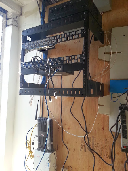
BEFORE:
Everything as it existed when I arrived.
FiOS modem will be removed, and a router will be bridged in its place. |
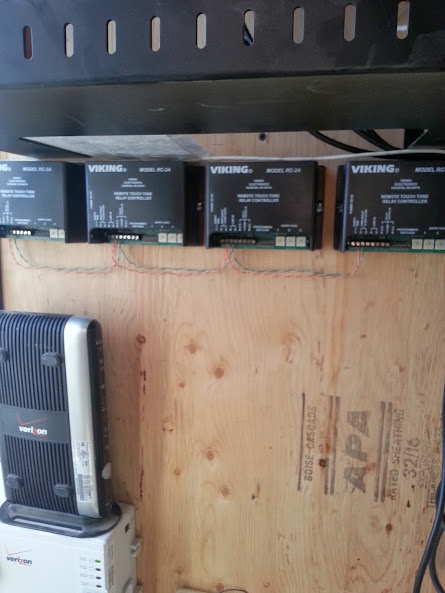 |
Mounted my 4 Viking RC2A devices below the rack
Wired up power jumpers. |
 |
| Added jacks to connect to analog line for each device. |
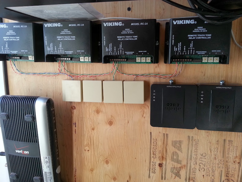 |
| Mounted 2 SPA112 devices for analog lines. |
 |
| Drilled hole at an angle up in drywall to snake to the drop ceiling. |
 |
| From same hole drilled out to the front of the building. |
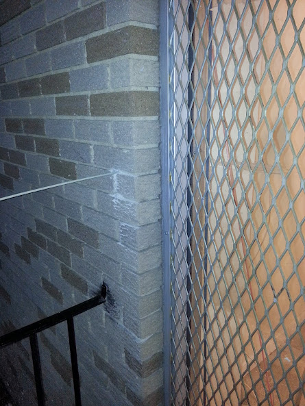 |
| Fish stick coming thru the brick from inside. |
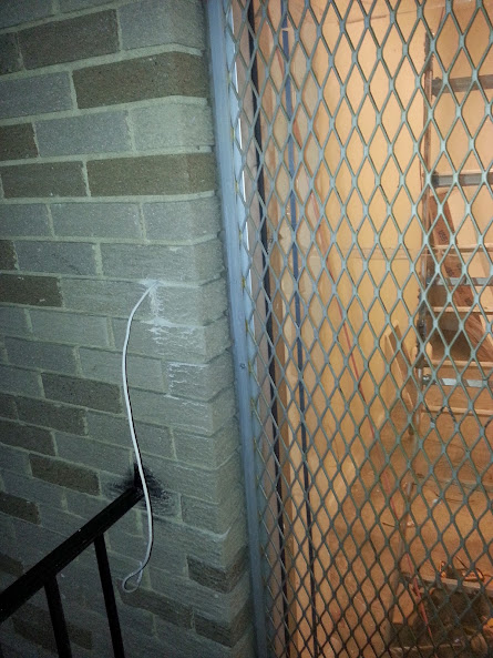 |
| Wire pulled thru from inside. |
 |
| As a point of reference showing how small the hole required is. |
 |
| Close up of my stick fished up towards the drop ceiling. |
 |
| Loop from drop ceiling going outside, slack will be pulled back up. |
 |
Wire in place, all that is left is a small hole,
smaller than the size of a quarter. |
Job is not complete, and additional photos may be added soon.
This job entailed installing 4 door phones, overhead paging, configuring about 6 VoIP phones that the customer provided, as well as installing a PoE switch that the customer provided. I also will be removing the FiOS router and replacing it with an actual router. I am uncertain of if we will use the Cisco/Linksys E1550 that the customer provided, or if we will go with an E2500, or an SRP router yet. I guess it depends on how well the E1550 handles the network.
Everything was supposed to be prewired, but of course the furthest door from the network room was not wired, and the guy who wired the door phone wiring just left everything in the drop ceilings, leaving the hard part (snaking down the walls and to the outside) for me to handle.

I saw the telephone color code on yahoo with your website on it, I have a 6 line jack but my phone is with 4 line. I did try to connect the line according to the picture I saw from your website but it's not working no dial tone, "totally no line". pls. help!!
ReplyDeleteconfused what you mean a "6 line" jack and a "4 line" phone.. I am unaware of any "6 line" jacks - that would be a total of 12 pins in the jack... I assume you mean your jack has 6 pins or a 3 line jack.
Deletethe jack should have red/green - which should be your line 1 - if it is a new color code wire, then your blue/white and solid blue should connect to these wires..
next would be yellow and black - this would connect to your orange/white and solid orange for line 2
finally there would be a blue and white pair - don't bother connecting anything to this because i doubt that you have any phones that would even use the 3rd pair of wires..
this is all assuming that there is dial tone on the wire that you are attempting to connect... if you are not afraid of a tiny shock, the fastest way i have found to tell if a line is live or not is to lick your finger and touch the pair you expect dial tone to be on... no shock no dial tone.. small shock then there is dial tone.. or you could use a continuity tester..