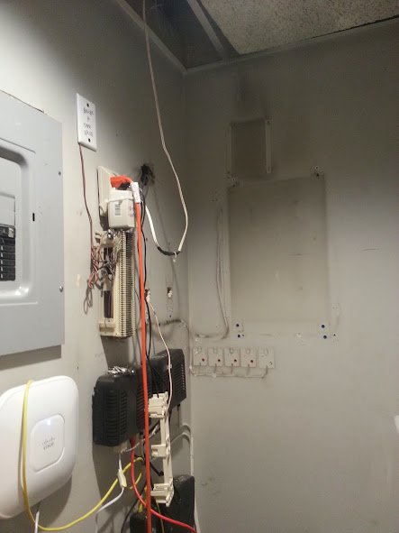
I first arrived at this job to find an ancient key phone system, and a somewhat messy "network" closet.
All of the computers were wired to this closed with long patch cords and hanging all over the place.
All of the computers were wired to this closed with long patch cords and hanging all over the place.
 |
| Existing network and old phone system |
 |
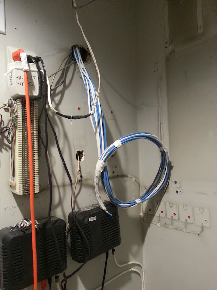
| Close up of existing wiring and phone system. |
I usually do not like removing any wiring blocks that previously existed, because it can be difficult to know what is still being used. Many times door relays, fax machines, or other low voltage systems are wired thru on the existing 66 blocks. I do occasionally will remove old phone systems or other no longer in use hardware.
 |
| Removed old key system and 2 66 blocks |
In this case the system was never in use by my customer. I was able to date the system to at least 1986 from a date that was stamped on the main board, as well as an inspection sticker located on the housing of the system. I was easily able to determine that 2 of the 66 blocks were only connected to this old system, and the station wiring (which will no longer be used). The other 66 block however appears to have at least some wiring for the door relays and possibly the existing intercom system, so I left that untouched.
 |
| New CAT5 wiring thru existing hole. |
There was plenty of holes in the wall already in the "network" closet, so I just used an existing hole to snake the wire down the wall.
4 additional runs need to be completed, 2 are going 2 flights down and 2 are going directly behind the network room. The patch panels and/or rack still need to be installed, and the switch and router needs to be properly mounted.
UPDATE:
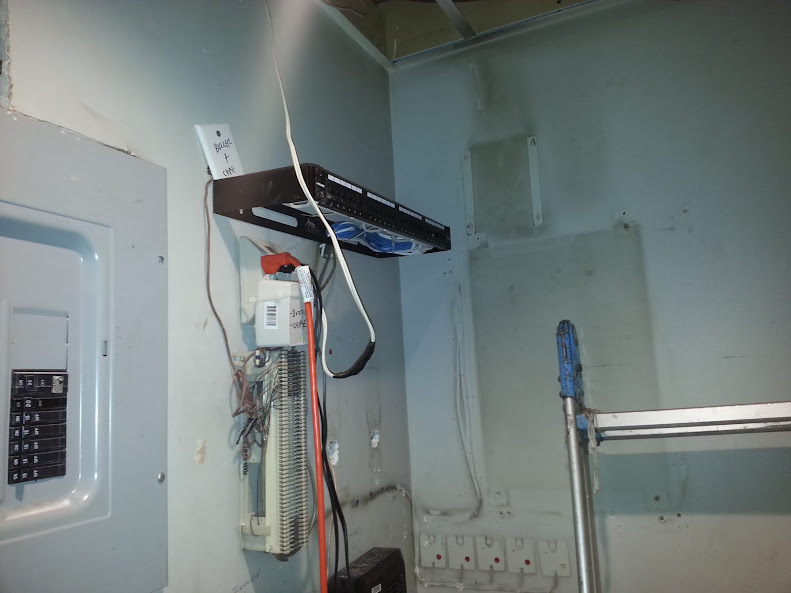
Day 2 brings with it the completion of the job. A 24 port patch panel was installed with a wall bracket. The remaining jacks and wiring was completed, and all jacks were labeled. I also mounted a 16 port switch, but by the time the jacks were labeled the computer tech had already installed his switch and started patching in the network for the PCs.
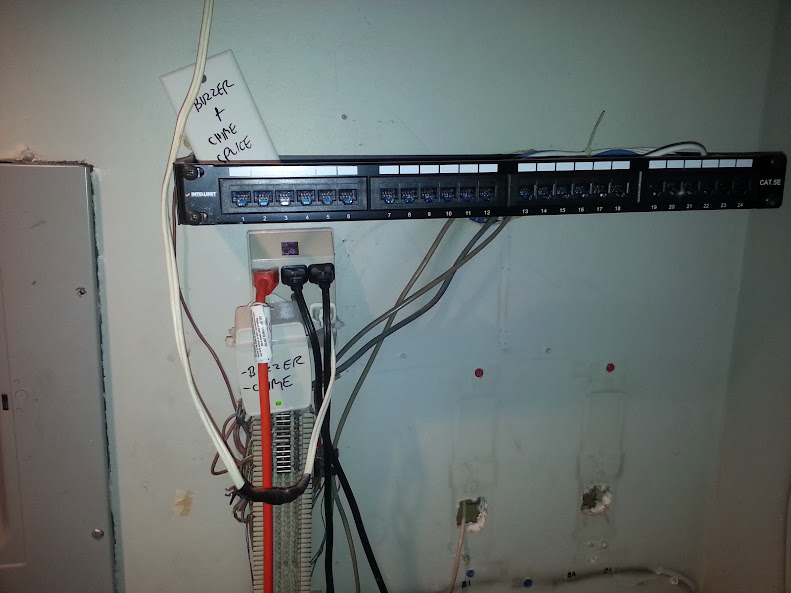
 |
| 24 port patch panel all punched down. (20 jacks in total) |
I do need to return to install a wall mount for one of the VoIP phones, as well as a PoE injector because the warehouse phone is not near a power outlet.
Another thing that did, which I attempt to do whenever there is time is that I printed out a spreadsheet of all of the jack numbers and their locations and left it by the patch panel. This can reduce the amount of time to install or troubleshoot issues - instead of having to crawl behind someones desk to see what number a jack is, the spreadsheet can be referenced to ensure the jack is properly patched into the right switch.