DUE TO ISSUES WITH GOOGLE PHOTOS ALL IMAGES AFTER AUGUST 2015 ARE NOT SHOWING, I AM TRYING TO FIGURE OUT HOW TO GET THIS WORKING!

Friday, October 25, 2013

the original social network


Reach out and touch someone,
let your fingers do the walking!

Wednesday, October 23, 2013

analog patch panel patches patched in

So one of our customers is a nursing home that is completing construction. It is a 4 story building with a telephone room on each floor. We used Grandstream 48 port, 24 port and 16 port ATA devices to provide each room with an analog station provided over VoIP. 
The patch panel before everything patched in.  
For some reason masking tape was covering many of the ports on the panel when we arrived today. Possibly to protect the pins from construction dust.

All patched in with 1 foot line cords.
(while it looks fairly neat, I really don't want to put my stamp of approval on this)
*One ATA still needs to be installed on this rack. 
The first day I went down to this location to patch everything in, my co-worker provided me with a box of 7 foot long line cords. These were excessively long, and I told him to get some shorter ones. He asked me if 3 footers was good, and I said yes, they would be perfect. Unfortunately He provided me with 1 footers for my return visit to patch everything in on the other floors of the building. While this looks fairly neat to the uninitiated, this is really not a very good way to patch things because now you have no access to work on the panel if anything needs to be repaired, added or changed with the wiring behind the panel without disconnecting everything.

Another floor at the same location patched in with 7 foot patch cords
While the cords are excessively long, This is more preferred than the 1 footers.

As you see with the 7 footers (3 footers would have been ideal) I was able to patch everything in and run along one side of the panel and back over. When you patch everything in this way it keeps things nice and neat, and also allows access to remove one of the patch panels in order to service any of the wiring, or add new wiring if needed in the future with limited, or no downtime for any of the active connections.

Bogen UTI312 install

Customer had 2 paging zones, and they wanted to integrate their VoIP phones with this paging system. The speakers and amplifiers were already installed when I arrived. I installed a Bogen UTI312 - named as such because it is a multi-zone Universal Telephone Interface that comes with a module for 3 paging zones, but is expandable up to 12 zones in total with the purchase and installation of additional modules (3 zones per module)

The analog line that connects to the UTI312 to connect it to the VoIP system comes from an SRP router that is mounted to the wall behind the rack. The dial tone from the analog device connects to the station port of the UTI312. The individual zones are connected to the output terminals on the UTI312 (blue wire in image for zone 1 and orange wire for zone 2) From the outputs of the UTI312 the wires are connected to the rear of the amplifiers into the TEL terminals. 

Paging is initiated by dialing into the extension of the analog device. The UTI312 auto-answers and provides an acknowledgement tone. Then the user can choose to page a single zone, or page all zones. To page all zones, once the UTI312 auto-answers the user enters 00, they will hear a more pronounced tone then can make their page. To page zone 1 the user would dial 01, and to page zone 2 the user would dial 02, etc all the way to 12 depending on how many zones are active on the device. For larger installations with multiple zones, zone groups can be set up on the device so that the user can enter a programmable access code to page multiple zones at the same time when they do not want to page all zones. 


UTI312 mounted below the 2 zone amplifiers.
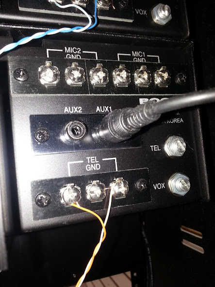
Terminations on the back of the amplifiers.
The paging inputs are connected to the TEL terminals.
Music, or any other source is connected to the AUX1 input.
When audio is detected on the TEL input all other inputs are muted
until there audio is no longer detected on the TEL input. 

2 doors wireless relay and keypads


This job was to install 2 door phones, a wireless relay for the doors, and keypads for 2 doors. The wires for the doors and the latches were already in place when work began. This took about 4 hours to complete. The hardware is mounted to the wall behind the network rack.

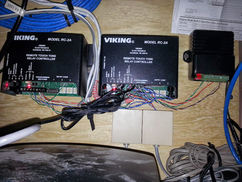
GREEN + ORANGE = POWER
BLUE + PURPLE = DIAL TONE
GRAY = N.O.
BLACK = COMMON (POWER)
RED = POWER TO LATCH
This image shows all devices getting power from one power supply,
and the release getting power from a second power supply.
If your power supply is weaker (lower mA rating) you may need a power supply for each relay.
If your power supply is stronger, you may be able to share power for the release and latch.


Monday, October 14, 2013

Valcom V-2001A and VoIP

We occasionally run across a few customers that require the installation of an overhead paging system. While we generally install Bogen UTI-1 devices for single zone paging applications, and UTI-312 devices for multi-zone paging applications we have come across several customers who have Valcom V-2001A devices already installed at their location.

These Devices are different in the Bogen devices in that while the Bogen device will work with an FXS device, the Valcom will not. The Valcom requires an FXO port.

Programming the 3102 to work with your VoIP service is beyond the scope of this article. Check with your VoIP provider, or the documentation for the IPPBX system that you are using for configuration of the device to work with your service.

Once the device is programmed properly, a simple test that can be performed to confirm that it is properly provisioned is to connect the LINE side of the device to a dial tone, then call into your 3102 - you should get the dial tone that the device is connected to, to confirm this disconnect the line cord from the line side of the device while you are on the call. You should immediately lose the dial tone.

Connecting a SPA3102 with the default settings will NOT work. You need to adjust the Busy detection setting under the PSTN tab. By default this is set to 30. I have found that by changing this setting to 20 everything will work properly. If you do not adjust this setting, the device will never connect to the device.

Before connecting the LINE side of the SPA 3102 to the V-2001a you should make sure that the switch next to the top jack that you will be connecting to is in the up position.