DUE TO ISSUES WITH GOOGLE PHOTOS ALL IMAGES AFTER AUGUST 2015 ARE NOT SHOWING, I AM TRYING TO FIGURE OUT HOW TO GET THIS WORKING!

Friday, November 22, 2013

Does Android 4.3 even exist?

UPDATE 12/1: After several phone calls, Tweets, and emails going back and fourth with Samsung and Sprint the update finally became available to me today on Kies. Not what I was expecting for an update that was supposed to be OTA only! Guess over the next few days I will see if the update was worth waiting over 8 days (or 10 days if you want to count the original release date)

Here is the email that I just sent to the CEO of Sprint, since his employees seem to be worthless.

I have been manually attempting to update my note 2 to android 4.3 since midnight 11/20 when it was originally released by sprint with no success. 

last night i called sprint care on the phone, and they advised me to call samsung for the update - obviously your reps were unaware that you delayed the update, this is unacceptable that your reps are not advised of changes in release dates regarding updates. 

samsung advised me to download kies and manually update to 4.3. unfortunately the update is not available to me on kies for one reason or another.

a return call to samsung and i was advised that i needed to contact my carrier, so when i called sprint care back, they WERE CLOSED!! 

so i took to twitter - and it seems each response is handled by a new person who did not take the time to read the thread and act like it is their first time learning about my struggles - and samsung had no idea that you delayed the release date!! very unacceptable!! 

i called back to sprint care today, and they give me this whole run around, one rep even told me that he has a samsung S3 running 4.2. I really dont give a fuck what kind of phone or version software your reps have or are using, i want them to resolve my issues, not talk faster than they can think. perhaps someone with fast talking and little knowledge about a product or service might make a decent salesman, but they make a terrible technical support representative. 

i was eventually advised by your reps that sprint CAN NOT PUSH THE UPDATE!!! they claim that it is samsung who needs to do that!! what a crock of horse shit! samsung delivers the update to YOU, and YOU are responsible to provide it to your customers, samsung has nothing to do with this transaction!

but just to cover all bases i contacted samsung to see what they had to say about this, and the fact remains - the update was provided to sprint, and it is sprint's responsibility to push that update to their customers. 

lets go! get this update sent out NOW! I have spent at least 10 hours over the last 3 days with phone calls, tweets, and attempting to manually update my phone OTA and with kies to no avail. at $50 per hour, that comes out to over $500 of my time that I have spent on something that should be so simple to accomplish within less than 20-30 minutes

Monday, November 18, 2013

4 door phone install + snaking wire with minimal damage to walls

BEFORE:
Everything as it existed when I arrived.
FiOS modem will be removed, and a router will be bridged in its place.
Mounted my 4 Viking RC2A devices below the rack
Wired up power jumpers.
Added jacks to connect to analog line for each device.
Mounted 2 SPA112 devices for analog lines. 
Drilled hole at an angle up in drywall to snake to the drop ceiling.
From same hole drilled out to the front of the building.
Fish stick coming thru the brick from inside.
Wire pulled thru from inside. 
As a point of reference showing how small the hole required is.
Close up of my stick fished up towards the drop ceiling. 
Loop from drop ceiling going outside, slack will be pulled back up. 
Wire in place, all that is left is a small hole,
smaller than the size of a quarter. 

Job is not complete, and additional photos may be added soon. 

This job entailed installing 4 door phones, overhead paging, configuring about 6 VoIP phones that the customer provided, as well as installing a PoE switch that the customer provided. I also will be removing the FiOS router and replacing it with an actual router. I am uncertain of if we will use the Cisco/Linksys E1550 that the customer provided, or if we will go with an E2500, or an SRP router yet. I guess it depends on how well the E1550 handles the network. 

Everything was supposed to be prewired, but of course the furthest door from the network room was not wired, and the guy who wired the door phone wiring just left everything in the drop ceilings, leaving the hard part (snaking down the walls and to the outside) for me to handle. 


Saturday, November 9, 2013

Spam comments.

I have always believed in free anonymous exchange of information, thoughts, ideas and comments.

I have always kept the comments on my blogs free from needing to sign up, or jump through any hoops in order for you to come here and post a comment, and have never deleted comments unless they were blatant spam and totally unrelated to the content of the blog.

However, as of lately many of the comments that I have been getting are spam related. Some obvious, others not so much (nonsense comments that make little sense, but still provide the spammers with back links)

I will be deleting all comments that I believe to be spam. This in no way is intended to restrict anyone's free and anonymous exchange of their thoughts or comments, and I will be removing ONLY comments that are spam. So feel free to continue to comment anonymously however you feel, even if you feel the need to hurl insults, as the only thing that will be removed from the comments from here forward will be spam related comments.

More doorphones + loudringer

Seems that lately I have been doing nothing but installing doorphones for customers. I had a huge inventory of doorphones and relays that I depleted within just the last week alone. 

Two SPA112 devices.
One is for 2 separate door phones
One is for 2 analog lines added to the door phone ring group.
One RC2A - only one of the doors that got a doorphone installed has a doorlatch,
the other door is always open during business hours and did not require a relay. 

Since the analog stations were placed within the warehouse so that workers
would be made aware when someone was ringing the door phone
a loud ringer had to be added above those phones so that people could hear
from anywhere in the warehouse that someone was at the door.
The customer picked these up on their own, and I am extremely impressed
with this model. All that is required is a connection to the phone line
it is powered by the ringing voltage of the phone line it is connected to. 


More doorphones and keypads installed

Front door and inside front door get their own relay,
Share a single phone line, and activate simultaneously
Upstairs office has its own relay and own phone line,
and acts independently.

Upstairs office has a doorphone (relay in above image)
and a keypad to activate the door latch. 

Buzzing a mantrap with a single user input

I have been installing many new VoIP systems and door releases in the diamond district lately. Just about every single office within the diamond district has a mantrap at the entrance. Basically a mantrap is a set of two doors. When one door is open the second door can not be open.


Configuring multiple relays like this are not limited to mantrap applications. If both doors are permitted to be opened at the same time the magnets can be removed from the configuration, and the wire going to the magnet can go directly to the door latch. Other possibilities would be for an electronic gate, or garage door that would automatically close - timings would need to be adjusted to allow sufficient time between cycles, and should be wired into a laser to ensure that the door does not close on anything that might not clear the gate/door. 

The image shows configuration with a doorphone, but this could easily be modifiable for any relay application, such as keychain FOBs. 

Friday, October 25, 2013

Wednesday, October 23, 2013

analog patch panel patches patched in

So one of our customers is a nursing home that is completing construction. It is a 4 story building with a telephone room on each floor. We used Grandstream 48 port, 24 port and 16 port ATA devices to provide each room with an analog station provided over VoIP. 
The patch panel before everything patched in.  
For some reason masking tape was covering many of the ports on the panel when we arrived today. Possibly to protect the pins from construction dust.

All patched in with 1 foot line cords.
(while it looks fairly neat, I really don't want to put my stamp of approval on this)
*One ATA still needs to be installed on this rack. 
The first day I went down to this location to patch everything in, my co-worker provided me with a box of 7 foot long line cords. These were excessively long, and I told him to get some shorter ones. He asked me if 3 footers was good, and I said yes, they would be perfect. Unfortunately He provided me with 1 footers for my return visit to patch everything in on the other floors of the building. While this looks fairly neat to the uninitiated, this is really not a very good way to patch things because now you have no access to work on the panel if anything needs to be repaired, added or changed with the wiring behind the panel without disconnecting everything.

Another floor at the same location patched in with 7 foot patch cords
While the cords are excessively long, This is more preferred than the 1 footers.

As you see with the 7 footers (3 footers would have been ideal) I was able to patch everything in and run along one side of the panel and back over. When you patch everything in this way it keeps things nice and neat, and also allows access to remove one of the patch panels in order to service any of the wiring, or add new wiring if needed in the future with limited, or no downtime for any of the active connections.

Bogen UTI312 install

Customer had 2 paging zones, and they wanted to integrate their VoIP phones with this paging system. The speakers and amplifiers were already installed when I arrived. I installed a Bogen UTI312 - named as such because it is a multi-zone Universal Telephone Interface that comes with a module for 3 paging zones, but is expandable up to 12 zones in total with the purchase and installation of additional modules (3 zones per module)

The analog line that connects to the UTI312 to connect it to the VoIP system comes from an SRP router that is mounted to the wall behind the rack. The dial tone from the analog device connects to the station port of the UTI312. The individual zones are connected to the output terminals on the UTI312 (blue wire in image for zone 1 and orange wire for zone 2) From the outputs of the UTI312 the wires are connected to the rear of the amplifiers into the TEL terminals. 

Paging is initiated by dialing into the extension of the analog device. The UTI312 auto-answers and provides an acknowledgement tone. Then the user can choose to page a single zone, or page all zones. To page all zones, once the UTI312 auto-answers the user enters 00, they will hear a more pronounced tone then can make their page. To page zone 1 the user would dial 01, and to page zone 2 the user would dial 02, etc all the way to 12 depending on how many zones are active on the device. For larger installations with multiple zones, zone groups can be set up on the device so that the user can enter a programmable access code to page multiple zones at the same time when they do not want to page all zones. 


UTI312 mounted below the 2 zone amplifiers.
Terminations on the back of the amplifiers.
The paging inputs are connected to the TEL terminals.
Music, or any other source is connected to the AUX1 input.
When audio is detected on the TEL input all other inputs are muted
until there audio is no longer detected on the TEL input. 

2 doors wireless relay and keypads


This job was to install 2 door phones, a wireless relay for the doors, and keypads for 2 doors. The wires for the doors and the latches were already in place when work began. This took about 4 hours to complete. The hardware is mounted to the wall behind the network rack.

GREEN + ORANGE = POWER
BLUE + PURPLE = DIAL TONE
GRAY = N.O.
BLACK = COMMON (POWER)
RED = POWER TO LATCH
This image shows all devices getting power from one power supply,
and the release getting power from a second power supply.
If your power supply is weaker (lower mA rating) you may need a power supply for each relay.
If your power supply is stronger, you may be able to share power for the release and latch.


Monday, October 14, 2013

Valcom V-2001A and VoIP

We occasionally run across a few customers that require the installation of an overhead paging system. While we generally install Bogen UTI-1 devices for single zone paging applications, and UTI-312 devices for multi-zone paging applications we have come across several customers who have Valcom V-2001A devices already installed at their location.

These Devices are different in the Bogen devices in that while the Bogen device will work with an FXS device, the Valcom will not. The Valcom requires an FXO port.

Programming the 3102 to work with your VoIP service is beyond the scope of this article. Check with your VoIP provider, or the documentation for the IPPBX system that you are using for configuration of the device to work with your service.

Once the device is programmed properly, a simple test that can be performed to confirm that it is properly provisioned is to connect the LINE side of the device to a dial tone, then call into your 3102 - you should get the dial tone that the device is connected to, to confirm this disconnect the line cord from the line side of the device while you are on the call. You should immediately lose the dial tone.

Connecting a SPA3102 with the default settings will NOT work. You need to adjust the Busy detection setting under the PSTN tab. By default this is set to 30. I have found that by changing this setting to 20 everything will work properly. If you do not adjust this setting, the device will never connect to the device.

Before connecting the LINE side of the SPA 3102 to the V-2001a you should make sure that the switch next to the top jack that you will be connecting to is in the up position.


Monday, September 9, 2013

24 port PoE switch and patch panel + CAT5 runs

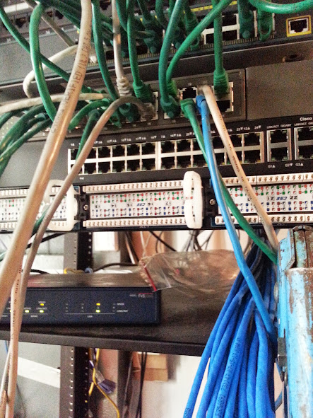
This customer already had an existing data network, and the panel was a bit messy. I installed a parallel network for their VoIP phones.  Not the worse that I have seen, but a mess of patch cords regardless. The customer has a network or IT technician that handles their data network, so I did not touch any of the data network patch cords, and all of their existing equipment was left as it was. 

All of the CAT5 runs that I did were surface mounted,
they were tywraped to conduit piping in the warehouse. 

With the mess of this active data network
I had to use caution when mounting my 24 port PoE switch
and my 24 port patch panel. 


Everything on this rack existed prior to me getting on site,
minus the 24 port switch and patch panel.
All green patch cords, and active routers/switches are for data network.

First 6 cables ready to be punched down. 

22 CAT5 wires terminated in my 24 port Patch panel. 

Had to use extra caution when flipping my patch panel over
after everything was punched in, because the data network was active.

All new jacks patched in. 

You may ask why did I use 3 foot patch cords instead of 1 footers, like the green ones that were used for the data network. First and foremost, patching everything in this way, and coming from the same side where the CAT5 is punched in to the panel allows for the panel to be removed from the rack to punch in additional jacks (there are 2 spaces available in the rack) as well as allowing for troubleshooting/repair of defective or improperly terminated wires. I also feel that it is more visually appealing and keeps things neater. Rarely will you see 1 foot patch cords in my bag of supplies. 

Oh, and in case you were wondering, all of the excess of the zip ties were clipped after taking this photograph. 

Out of time constraints, jacks were NOT tested and labeled, but I did patch everything in so that the panel port number and switch port number are the same, so that Labeling can easily be completed in the future with out the need for a tester or meter. All phones registered and got power from the PoE switch, so there were no failures. Testing and labeling would have taken at least an hour or two. Since there are no failures, I can easily have everything labeled within 20 minutes on a future visit.


Saturday, August 17, 2013

Painting my electrical panel chrome

My electrical panel cover had at least 2 coats of different colors from previous paint jobs in the house. Much  of it was uneven, and not smooth, because of the paint running. 


So there is some white paint, and some peach paint on the electrical panel cover, no good. 
Instead of trying to paint it the same color as the wall to try to hide it, I thought why not just make it stand out, sort of like a piece of art on the wall. What better way than to make it chrome!


I began the long and difficult task of removing all of the paint on the cover down to the bare metal, so that everything would even out. 


The drill got very hot during this process, since I leave my "real" drill at work, and had to resort to using an ancient drill with metal casing. This required me to stop several times during the process of removing all of the paint. 


It was important however to ensure that all of the paint was removed, so that I had a nice smooth surface for the final product.


As you see, not only was there white paint and peach paint on the cover, but there was also some blue paint from the last time that the walls were painted. 


The cover looks great with the paint all removed, and If I was not so concerned with leaving bare metal on my electrical panel, I might have opted for just leaving it like this.


The only thing left untouched is the original sticker on the inside of the door. 


On to the outside, where I sprayed a few coats of gray primer on the bare metal. This ensures that the paint will adhere to the surface, and in choosing the grey primer over other colors ensures a close enough base color to the chrome for the best results for the final product. 


Several coats of the chrome paint, and you can see my reflection in the cover. 


This is a project that I had wanted to do for at least a year, but never had the time to get around to it. Who knew that something as simple as removing the paint from an electric panel cover, and then respraying it would be such a difficult task? 


Finally it has been mounted on my wall. The only defects in the paint are from where I prematurely touched it before the paint fully dried. 


The photographs taken inside of my home do not do justice to the quality of the final product, which is as close to a chrome finish that I could have ever expected without sending it in to get chrome plated. The photo with the spray can makes the finish appear to be more silver than chrome, and not very reflective, but take a look at the image just above that, where you can see the reflection of my front door in the cover. 


Obsolete Telecom equipment removed from a customers location

I love the history of old telecom equipment, and whenever there is something obsolete that is only going to find its way into a dumpster, because it is no longer useful in the modern world I usually save it from going to a dump. 

So is the case with this piece of equipment that was removed from one of my customers, that I was at installing a new data network for IP phones. 

Oh, and it's for sale if anyone has any use for it, or just collects telecom nostalgia. 


Another small patch panel install (3X 12 port panels)

With this install I the customer had already had most of the wiring in place. I only pulled double CAT 5 runs to 3 locations within the office. 

Due to space restraints where the wiring was installed I opted for 3 - 12 port "66 block mount style" patch panels. 

For this job I toned out all of the wiring prior to punching them down so that the A and B jacks at each location would have the same number at each location.