DUE TO ISSUES WITH GOOGLE PHOTOS ALL IMAGES AFTER AUGUST 2015 ARE NOT SHOWING, I AM TRYING TO FIGURE OUT HOW TO GET THIS WORKING!

Wednesday, October 23, 2013

Bogen UTI312 install

Customer had 2 paging zones, and they wanted to integrate their VoIP phones with this paging system. The speakers and amplifiers were already installed when I arrived. I installed a Bogen UTI312 - named as such because it is a multi-zone Universal Telephone Interface that comes with a module for 3 paging zones, but is expandable up to 12 zones in total with the purchase and installation of additional modules (3 zones per module)

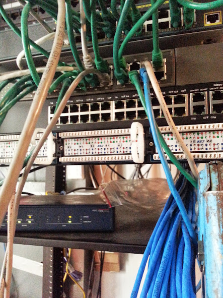
The analog line that connects to the UTI312 to connect it to the VoIP system comes from an SRP router that is mounted to the wall behind the rack. The dial tone from the analog device connects to the station port of the UTI312. The individual zones are connected to the output terminals on the UTI312 (blue wire in image for zone 1 and orange wire for zone 2) From the outputs of the UTI312 the wires are connected to the rear of the amplifiers into the TEL terminals. 

Paging is initiated by dialing into the extension of the analog device. The UTI312 auto-answers and provides an acknowledgement tone. Then the user can choose to page a single zone, or page all zones. To page all zones, once the UTI312 auto-answers the user enters 00, they will hear a more pronounced tone then can make their page. To page zone 1 the user would dial 01, and to page zone 2 the user would dial 02, etc all the way to 12 depending on how many zones are active on the device. For larger installations with multiple zones, zone groups can be set up on the device so that the user can enter a programmable access code to page multiple zones at the same time when they do not want to page all zones. 


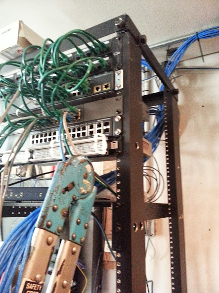
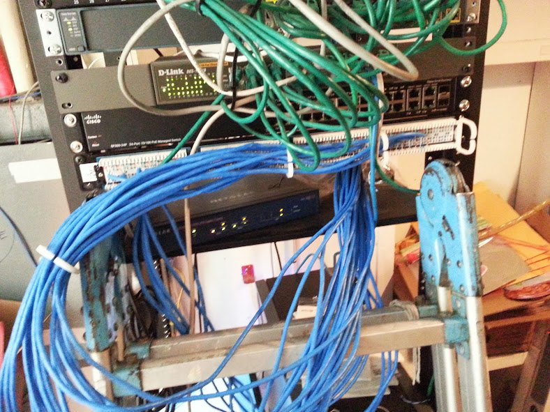
UTI312 mounted below the 2 zone amplifiers.
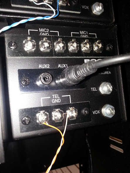
Terminations on the back of the amplifiers.
The paging inputs are connected to the TEL terminals.
Music, or any other source is connected to the AUX1 input.
When audio is detected on the TEL input all other inputs are muted
until there audio is no longer detected on the TEL input. 

2 doors wireless relay and keypads


This job was to install 2 door phones, a wireless relay for the doors, and keypads for 2 doors. The wires for the doors and the latches were already in place when work began. This took about 4 hours to complete. The hardware is mounted to the wall behind the network rack.

GREEN + ORANGE = POWER
BLUE + PURPLE = DIAL TONE
GRAY = N.O.
BLACK = COMMON (POWER)
RED = POWER TO LATCH
This image shows all devices getting power from one power supply,
and the release getting power from a second power supply.
If your power supply is weaker (lower mA rating) you may need a power supply for each relay.
If your power supply is stronger, you may be able to share power for the release and latch.


Monday, October 14, 2013

Valcom V-2001A and VoIP

We occasionally run across a few customers that require the installation of an overhead paging system. While we generally install Bogen UTI-1 devices for single zone paging applications, and UTI-312 devices for multi-zone paging applications we have come across several customers who have Valcom V-2001A devices already installed at their location.

These Devices are different in the Bogen devices in that while the Bogen device will work with an FXS device, the Valcom will not. The Valcom requires an FXO port.

Programming the 3102 to work with your VoIP service is beyond the scope of this article. Check with your VoIP provider, or the documentation for the IPPBX system that you are using for configuration of the device to work with your service.

Once the device is programmed properly, a simple test that can be performed to confirm that it is properly provisioned is to connect the LINE side of the device to a dial tone, then call into your 3102 - you should get the dial tone that the device is connected to, to confirm this disconnect the line cord from the line side of the device while you are on the call. You should immediately lose the dial tone.

Connecting a SPA3102 with the default settings will NOT work. You need to adjust the Busy detection setting under the PSTN tab. By default this is set to 30. I have found that by changing this setting to 20 everything will work properly. If you do not adjust this setting, the device will never connect to the device.

Before connecting the LINE side of the SPA 3102 to the V-2001a you should make sure that the switch next to the top jack that you will be connecting to is in the up position.


Monday, September 9, 2013

24 port PoE switch and patch panel + CAT5 runs

This customer already had an existing data network, and the panel was a bit messy. I installed a parallel network for their VoIP phones.  Not the worse that I have seen, but a mess of patch cords regardless. The customer has a network or IT technician that handles their data network, so I did not touch any of the data network patch cords, and all of their existing equipment was left as it was. 

All of the CAT5 runs that I did were surface mounted,
they were tywraped to conduit piping in the warehouse. 

With the mess of this active data network
I had to use caution when mounting my 24 port PoE switch
and my 24 port patch panel. 


Everything on this rack existed prior to me getting on site,
minus the 24 port switch and patch panel.
All green patch cords, and active routers/switches are for data network.

First 6 cables ready to be punched down. 

22 CAT5 wires terminated in my 24 port Patch panel. 

Had to use extra caution when flipping my patch panel over
after everything was punched in, because the data network was active.

All new jacks patched in. 

You may ask why did I use 3 foot patch cords instead of 1 footers, like the green ones that were used for the data network. First and foremost, patching everything in this way, and coming from the same side where the CAT5 is punched in to the panel allows for the panel to be removed from the rack to punch in additional jacks (there are 2 spaces available in the rack) as well as allowing for troubleshooting/repair of defective or improperly terminated wires. I also feel that it is more visually appealing and keeps things neater. Rarely will you see 1 foot patch cords in my bag of supplies. 

Oh, and in case you were wondering, all of the excess of the zip ties were clipped after taking this photograph. 

Out of time constraints, jacks were NOT tested and labeled, but I did patch everything in so that the panel port number and switch port number are the same, so that Labeling can easily be completed in the future with out the need for a tester or meter. All phones registered and got power from the PoE switch, so there were no failures. Testing and labeling would have taken at least an hour or two. Since there are no failures, I can easily have everything labeled within 20 minutes on a future visit.