So I was dispatched to this "small" installation of about 10 double cat5 runs (20 wires/jacks)
 |
| There were numerous cross beams I had to channel around. |
It should have been completed within a single day, especially the first day I was at this job I had assistance.
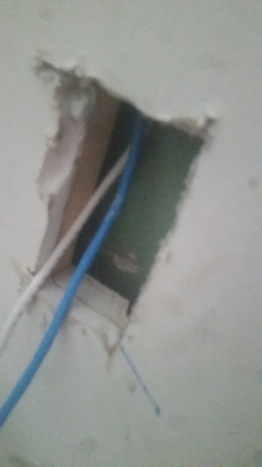 |
| The entire office had half inch paneling underneath the sheetrock. |
The problem was that behind the sheetrock walls there was half inch solid wood paneling. I had to use my sawzall to cut open every single jack opening to snake the wires thru and connect the jacks.
 |
| Close up of channeling around a cross beam. |
Not only was there solid wood paneling directly behind the sheetrock, but because of this there was many cross beams that I had to channel around to get the wire down the wall.
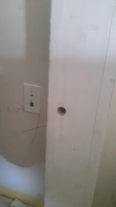 |
Used pipe chase to snake the wire to this jack.
Hole cut to snake it behind paneling over to jack. |
There was a pipe chase that I was able to snake wires down for one of the jacks, saving me from having to channel around 3 cross beams, I instead just had to cut a hole in the chase to snake the wire down, then across to the jack opening.
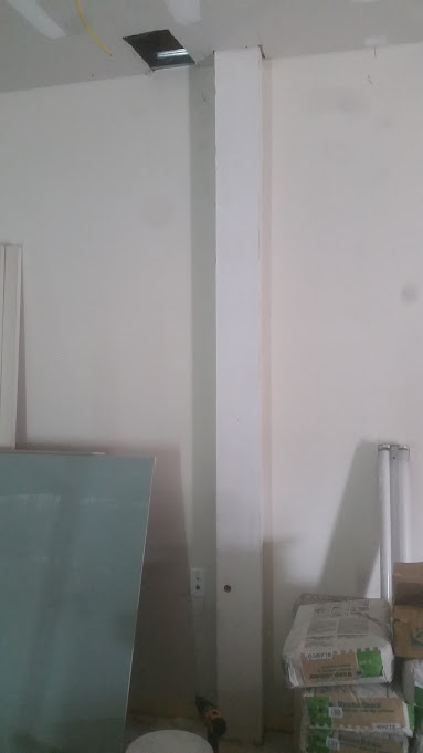 |
| Ceilings had to be open for wire to be snaked down pipe chase. |
Finally, one jack was on the wall directly behind the staircase going upstairs. I spent nearly 2 hours trying to open the plaster behind the sheetrock, and get a snake up or down this wall, but the beam for the staircase just wouldn't allow me to get down inside this wall.
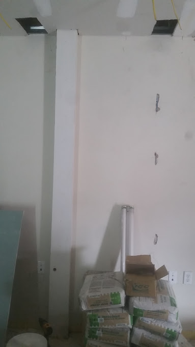 |
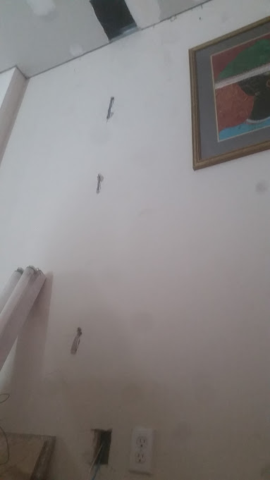
| Wide angle of required wall openings. |
The only option was surface mounting the wire. Luckily behind this jack was the staircase for the basement, so the wire molding that I ended up having to install is pretty much hidden from daily view.
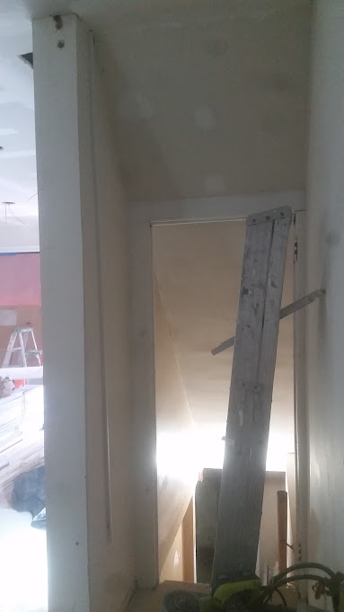 |
I tried for hours to snake down this wall,
unfortunately because of the staircase beam it was impossible,
so wiremolding was used. |
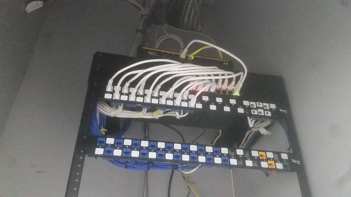
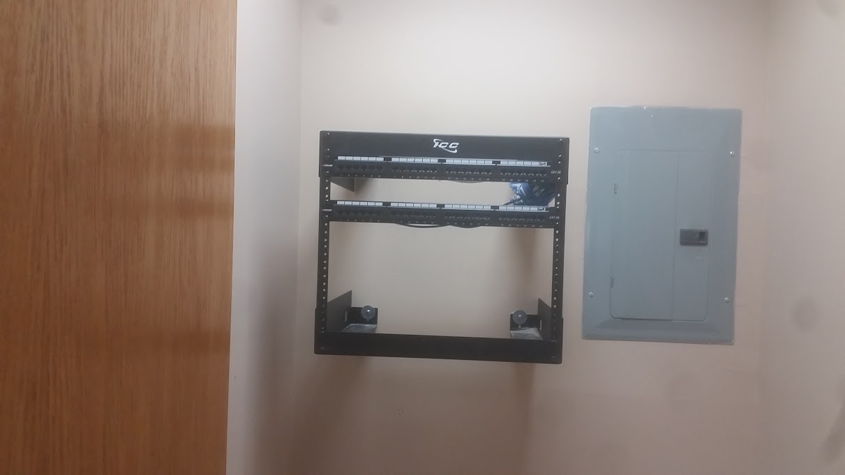
Finally I installed the patch panel and bracket low to the ground because the customer wanted to put in a cabinet to cover/hide it.
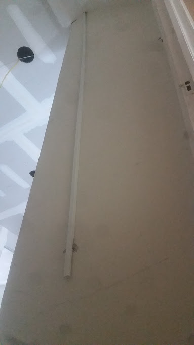 |
You can hardly see where the wire goes into the ceiling,
or comes in thru the wall. |
I would have prefered to install a rack, but then again, I always prefer to install a rack. It keeps things neat and organized, and just looks much more professional. But for some of these smaller installations it is difficult for the customer to justify the extra expense or space for installing a rack.
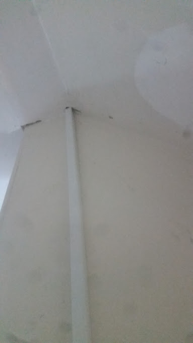 |
| Close up of wire molding going to ceiling. |
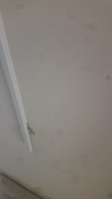 |
| Close up of wire molding at bottom, opposite side of wall as jack. |
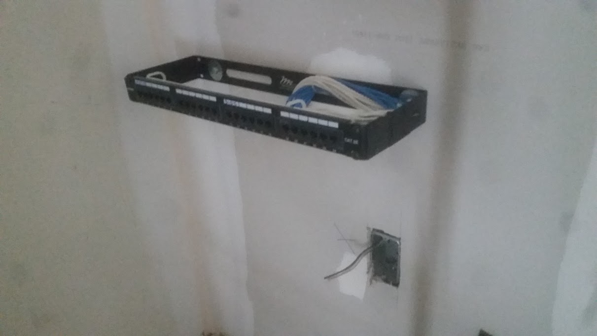 |
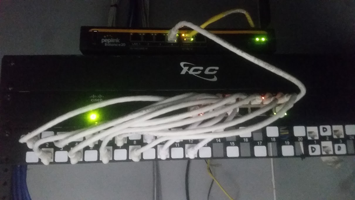
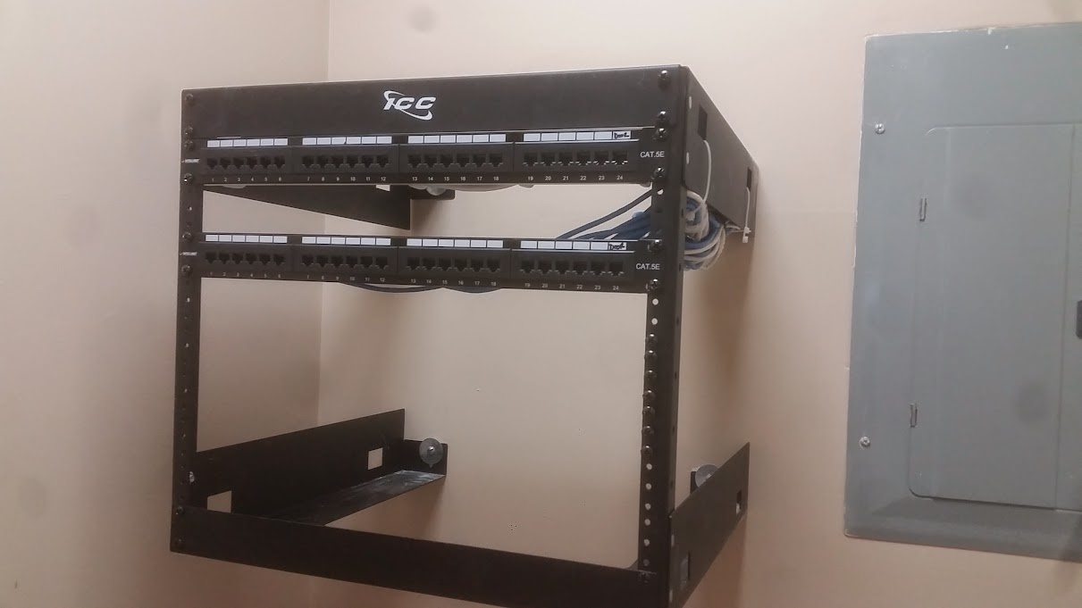
| 24 port patch panel. |
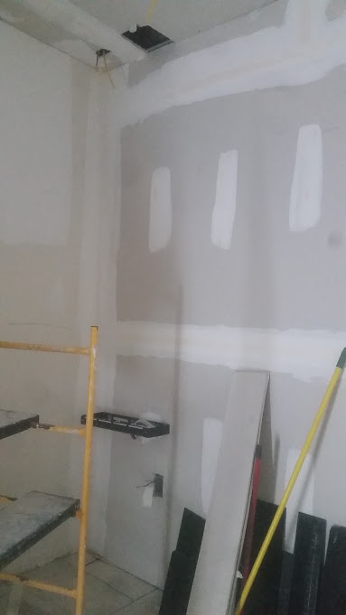 |
| Wide angle of patch panel. |